
 EN
 AR
 BG
 HR
 CS
 DA
 NL
 FI
 FR
 DE
 EL
 HI
 IT
 JA
 KO
 NO
 PL
 PT
 RO
 RU
 ES
 SV
 TL
 IW
 ID
 LT
 UK
 SQ
 HU
 TH
 TR
 FA
 AF
 CY
 MK
 LA
 MN
 KK
 UZ
 KY

An igbt inverter welder operates at the cutting edge of modern welding technology, using sophisticated high-frequency switching mechanisms to deliver superior arc control and energy efficiency. Understanding how an igbt inverter welder manages this switching process is crucial for professionals seeking to maximize weld quality and operational performance. The rapid switching action within an igbt inverter welder determines its responsiveness, thermal management, and overall welding capability across diverse applications.
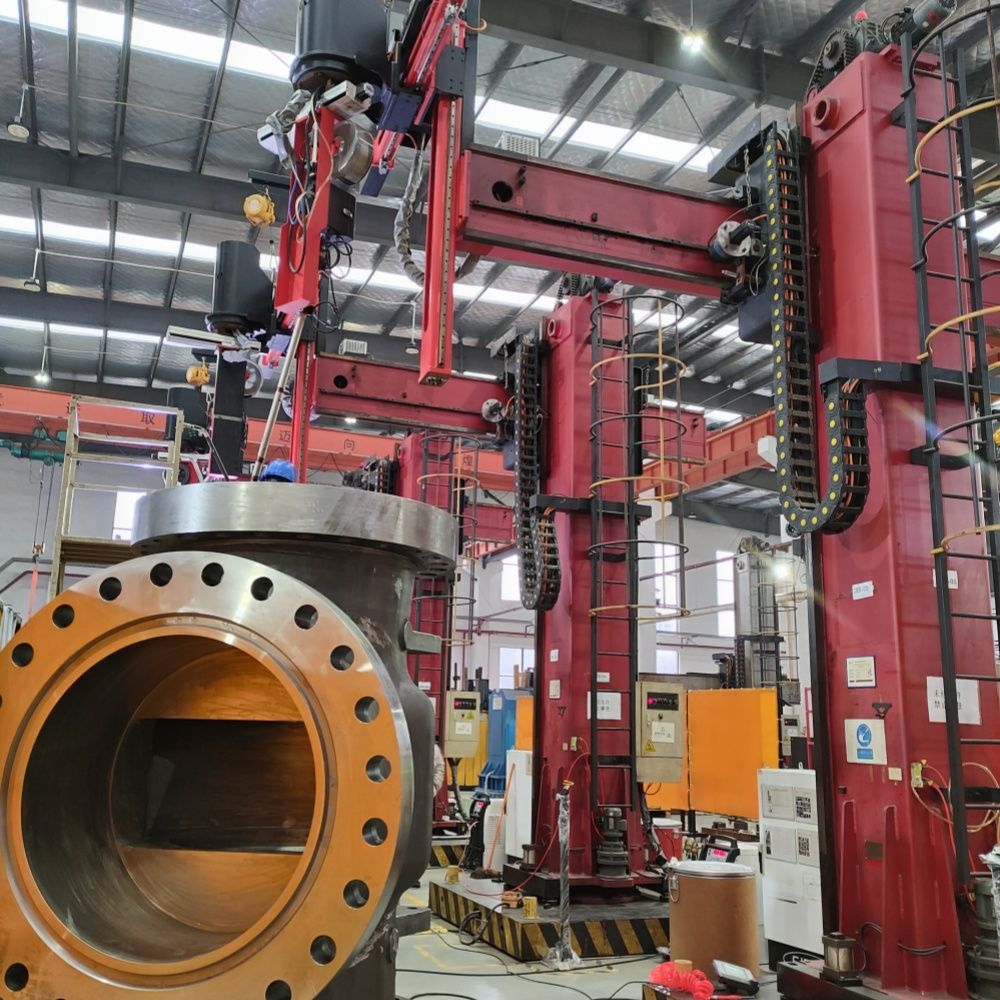
The igbt inverter welder represents a fundamental departure from traditional transformer-based welding machines. Instead of relying on heavy copper and iron cores to step down voltage, an igbt inverter welder uses transistor-based switching at frequencies typically between 5 kHz and 200 kHz to regulate power delivery. This high-frequency architecture enables the igbt inverter welder to achieve exceptional arc stability, faster response times, and dramatically reduced machine weight compared to older technologies.
The Core Switching Technology Behind IGBT Inverter Welder Architecture
Understanding the IGBT Switching Circuit
At the heart of every igbt inverter welder lies the Insulated Gate Bipolar Transistor, a semiconductor device that functions as a controllable electronic switch. An igbt inverter welder relies on these transistors to rapidly turn the primary welding power on and off, typically thousands of times per second. This switching action allows an igbt inverter welder to modulate the power flowing into the welding transformer, effectively controlling output voltage and current with precision that transformer-based systems cannot match. The gate signal applied to each IGBT within an igbt inverter welder determines exact switching timing, enabling real-time adjustments to match arc conditions.
Frequency Range and Performance
An igbt inverter welder typically operates at switching frequencies between 5 kHz and 200 kHz, depending on design and welding application. Higher switching frequencies in an igbt inverter welder allow smaller transformer cores and filter components, directly reducing machine size and weight. An igbt inverter welder operating at 50 kHz achieves fundamentally different thermal behavior than one running at 10 kHz. The switching frequency chosen for an igbt inverter welder affects electromagnetic interference, cooling requirements, and arc response time. Most modern an igbt inverter welder designs balance frequency against component stress and manufacturing cost, settling on frequencies that optimize performance for their target welding processes.
Arc Control and Power Modulation in IGBT Inverter Welder Systems
Real-Time Arc Response Mechanism
An igbt inverter welder continuously monitors arc voltage and current, then adjusts its switching pulse width within microseconds to maintain stable output. This closed-loop response capability distinguishes an igbt inverter welder from older systems where adjustment required manual control or slow mechanical feedback. When arc length fluctuates, an igbt inverter welder detects the voltage change and immediately alters the duty cycle of its switching circuit to compensate. This rapid correction prevents spatter, maintains penetration consistency, and reduces defects—benefits that make an igbt inverter welder the preferred choice for precision applications including stainless steel, aluminum, and cladding work. An igbt inverter welder's ability to respond in milliseconds means operators experience more forgiving machines that tolerate variation in travel speed and technique.
Duty Cycle and Output Regulation
An igbt inverter welder controls output power by varying the duty cycle—the fraction of time each IGBT remains switched on during a cycle. An igbt inverter welder with a 50% duty cycle delivers half the theoretical maximum power, while 100% duty cycle delivers full power. By continuously adjusting this duty cycle, an igbt inverter welder achieves smooth power gradation from minimum to maximum settings. An igbt inverter welder's output current appears nearly constant despite input voltage variations, a characteristic known as constant current output. This stability is essential for stick and TIG welding, where arc length changes would otherwise cause uncontrolled current swings. An igbt inverter welder accomplishes this regulation electronically rather than through magnetic properties, offering faster response and wider adjustment range than traditional designs.
Thermal Management and Efficiency in IGBT Inverter Welder Design
Heat Dissipation and Component Protection
The switching action within an igbt inverter welder generates heat both in the IGBT devices themselves and in associated components like freewheeling diodes and filters. An igbt inverter welder must dissipate this heat efficiently to maintain safe junction temperatures and extend component lifespan. Most commercial igbt inverter welder designs incorporate aluminum heatsinks with forced-air cooling, sometimes supplemented by phase-change thermal interface materials. An igbt inverter welder typically monitors IGBT junction temperature and throttles output or activates higher fan speed when thermal limits approach. This active thermal management ensures an igbt inverter welder can operate continuously in hot environments without performance degradation. Advanced igbt inverter welder models include temperature sensors that feed back into the control circuit, enabling predictive thermal management that prevents nuisance shutdowns.
Energy Efficiency Advantages
An igbt inverter welder achieves electrical efficiency typically between 85% and 92%, compared to 60–75% for transformer-based machines. This efficiency advantage arises because an igbt inverter welder eliminates core losses from large transformer iron and reduces resistive losses through smaller, higher-efficiency components. An igbt inverter welder consumes less utility power to deliver the same welding output, directly reducing energy costs and heat generation in the workshop. An igbt inverter welder's efficiency advantage becomes particularly important in high-production environments where machines operate 8–12 hours daily. The reduced cooling burden means an igbt inverter welder requires less ventilation and creates a more comfortable working environment. For battery-powered or portable welding applications, the efficiency of an igbt inverter welder extends runtime and reduces battery mass.
Practical Application and Selection Considerations
Suitability for Various Welding Processes
An igbt inverter welder excels across multiple welding processes including TIG, MMA (stick), and MIG/MAG spray transfer modes. The precise arc control inherent to an igbt inverter welder makes it particularly suited for aluminum and stainless steel where defect-free welds require exceptional consistency. An igbt inverter welder's compact form factor makes it the default choice for portable and site-based applications where space and weight constraints exclude transformer machines. For cladding and overlay work, the controlled heat input characteristic of an igbt inverter welder prevents dilution and heat-affected zone distortion. An igbt inverter welder also enables advanced features like controlled ramp-up and ramp-down of current, slope control, and multi-process switching that rely on rapid transistor response.
Industrial Decision Factors
Selecting an igbt inverter welder requires consideration of operating duty cycle, ambient temperature, power supply stability, and required features. An igbt inverter welder rated for continuous 100% duty provides maximum flexibility but costs more than 60% duty machines. An igbt inverter welder must be matched to available incoming power; three-phase supply allows smaller, more efficient designs than single-phase. An igbt inverter welder operating in high-dust or high-humidity environments requires robust air filtration to prevent component fouling. The switching frequency of an igbt inverter welder affects electromagnetic compatibility; sensitive equipment nearby may require shielding if using high-frequency models. Budget-conscious operations may choose basic igbt inverter welder models with essential features, while demanding applications benefit from premium units with advanced monitoring and diagnostic capability.
FAQ
What is the primary advantage of high-frequency switching in an igbt inverter welder?
The primary advantage of high-frequency switching in an igbt inverter welder is the dramatic reduction in machine size and weight while maintaining superior arc control. High-frequency switching allows an igbt inverter welder to use much smaller transformer cores and filter components compared to 50–60 Hz systems, making portability practical. Additionally, high-frequency switching in an igbt inverter welder enables microsecond-level response to arc disturbances, preventing spatter and improving weld appearance. An igbt inverter welder's high-frequency switching architecture also delivers exceptional power efficiency, reducing operational energy costs and cooling requirements.
How does an igbt inverter welder maintain constant current output despite input voltage variations?
An igbt inverter welder maintains constant current output through closed-loop feedback control that continuously monitors arc voltage and adjusts the switching duty cycle within milliseconds. When supply voltage fluctuates, an igbt inverter welder's control circuit immediately compensates by changing the on-time of its switching transistors, effectively regulating power delivery. This electronic regulation happens so rapidly that downstream arc conditions remain nearly constant even when line voltage varies significantly. An igbt inverter welder accomplishes this without mechanical adjustment, making it far more responsive than transformer machines that rely on magnetic coupling and tap switching.
What maintenance considerations apply to the high-frequency switching components in an igbt inverter welder?
Maintenance of an igbt inverter welder's high-frequency switching components primarily focuses on thermal management and cleanliness. An igbt inverter welder requires regular air filter inspection and cleaning because dust accumulation on heatsink fins reduces cooling effectiveness and can lead to component failure. An igbt inverter welder's IGBT devices degrade gradually under thermal stress; keeping junction temperatures within design limits extends lifespan significantly. Most commercial igbt inverter welder designs include replaceable filter cartridges and fan assemblies; these should be serviced according to manufacturer intervals. An igbt inverter welder operated in wet or corrosive environments requires more frequent inspection of electrical connections to prevent corrosion-related failures in gate drive circuits.