
 EN
 AR
 BG
 HR
 CS
 DA
 NL
 FI
 FR
 DE
 EL
 HI
 IT
 JA
 KO
 NO
 PL
 PT
 RO
 RU
 ES
 SV
 TL
 IW
 ID
 LT
 UK
 SQ
 HU
 TH
 TR
 FA
 AF
 CY
 MK
 LA
 MN
 KK
 UZ
 KY
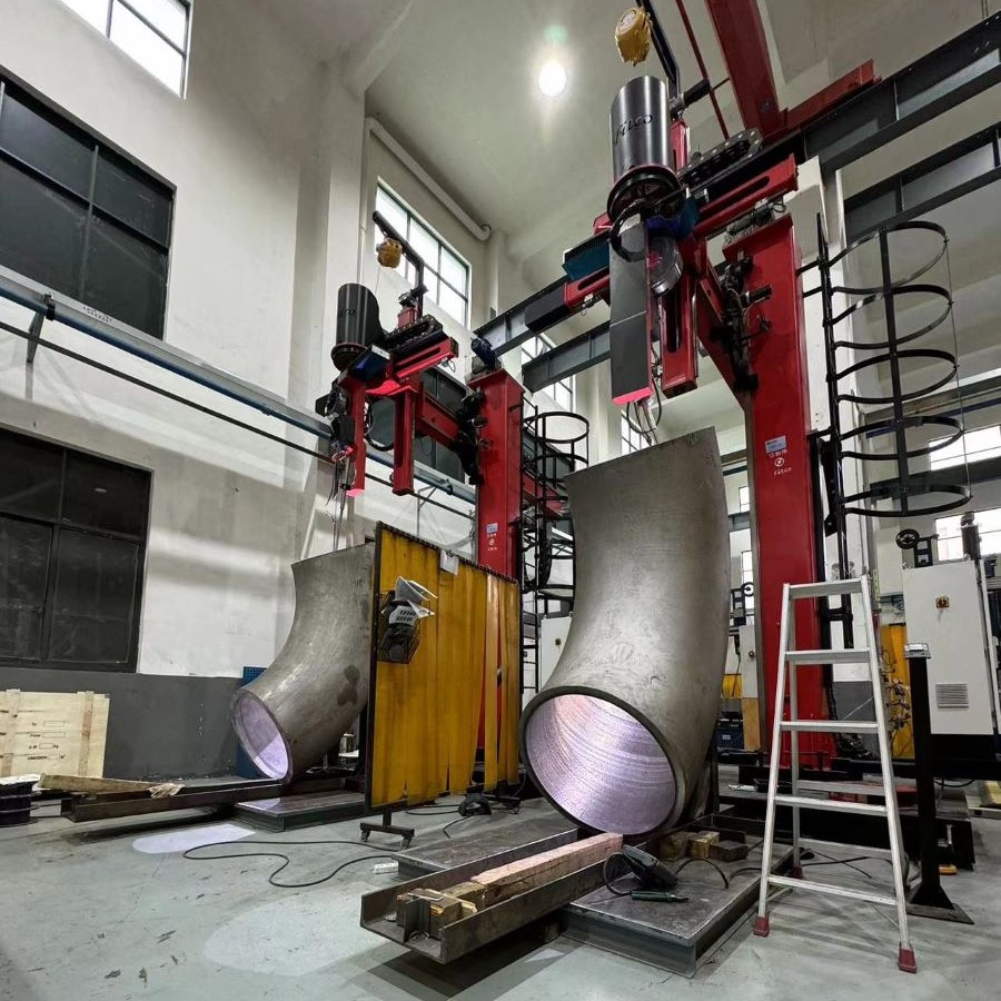
Pulse welding represents one of the most advanced techniques in modern fabrication, and proper calibration of your mig welding equipment is absolutely essential for achieving optimal results. When your mig welding equipment operates with incorrect parameters, you face inconsistent arc performance, poor penetration, and compromised weld bead geometry. The calibration process for pulse welding differs significantly from standard constant-voltage MIG processes, requiring specific attention to multiple interdependent variables. This guide walks you through the complete calibration procedure to ensure your mig welding equipment delivers the precision and reliability your industrial applications demand.

Your mig welding equipment operates through a complex interaction of electrical, mechanical, and gas-delivery systems. Understanding how each component contributes to pulse welding performance is the foundation of successful calibration. When these systems work in harmony, your mig welding equipment produces cleaner welds with reduced spatter, lower heat input, and superior control, especially on thin materials and out-of-position applications. Proper calibration transforms your mig welding equipment from a general-purpose tool into a precision instrument capable of meeting the strictest quality standards.
Understanding Pulse Welding Parameters for MIG Equipment
The Role of Peak and Background Current
Pulse welding fundamentally changes how your mig welding equipment operates by cycling between high peak currents and lower background currents at controlled frequencies. The peak current determines how quickly the weld pool forms and how deeply the arc penetrates into the base metal. Your mig welding equipment must deliver consistent peak current to ensure uniform droplet transfer and stable arc characteristics. The background current maintains the arc between pulses without allowing it to extinguish, and this parameter critically affects your mig welding equipment's ability to handle different material thicknesses and joint configurations.
The frequency at which your mig welding equipment cycles between peak and background current directly influences the resulting weld quality and appearance. Higher frequencies with your mig welding equipment typically produce finer, more refined bead surfaces, while lower frequencies may generate larger droplets and more pronounced ripple patterns. Modern mig welding equipment often provides adjustable frequency settings, typically ranging from 30 to 300 Hz, allowing you to optimize performance for specific applications. When your mig welding equipment cycles at the correct frequency for your material and wire diameter, you achieve what professionals call 'one-drop-per-pulse' transfer, the gold standard in controlled metal deposition.
Voltage and Wire Feed Speed Interaction
Voltage settings on your mig welding equipment control the arc length and directly impact weld bead width and appearance. Too low voltage causes your mig welding equipment to produce narrow, ropey beads with poor fusion, while excessive voltage creates wide, convex beads prone to undercut defects. The voltage window for your mig welding equipment is typically narrower in pulse mode than in conventional MIG, requiring more precise adjustment. Wire feed speed must work in concert with voltage; your mig welding equipment uses this combination to determine the actual heat input and metal deposition rate into the weld pool.
When calibrating your mig welding equipment, you must recognize that voltage and wire feed speed are not independent variables. Increasing wire feed speed on your mig welding equipment typically requires proportional voltage adjustment to maintain proper arc characteristics. Most modern mig welding equipment includes preset tables or adaptive controls that automatically correlate these parameters based on wire diameter and material type. However, understanding the relationship allows you to make intelligent manual adjustments when your mig welding equipment encounters unique joint configurations or material conditions that fall outside standard parameters.
Step-by-Step Calibration Process for Your MIG Welding Equipment
Initial Setup and Reference Material Selection
Begin calibration of your mig welding equipment by ensuring all external connections are clean and tight, as poor electrical contact reduces the precision of voltage regulation and limits what your mig welding equipment can achieve. Select reference material that matches your actual production requirements; your mig welding equipment calibration should target the specific carbon steel, stainless steel, or aluminum you regularly weld. Check that your mig welding equipment's gas delivery system is functioning correctly and that shielding gas purity meets specifications, typically 99.95% for argon-based mixtures. Contaminated or impure gas flowing through your mig welding equipment will prevent accurate calibration because it creates unstable arcs regardless of electrical parameter settings.
Mount your reference test piece securely in a position that represents your typical welding orientation. If your mig welding equipment primarily operates in the flat position, calibrate primarily in that orientation, though you should test vertical and overhead positions after establishing your baseline settings. Inspect the contact tip and liner of your mig welding equipment to ensure they are clean, properly sized for your wire diameter, and centered in the gun. A worn contact tip on your mig welding equipment can introduce erratic contact resistance that makes calibration impossible because the equipment interprets electrical noise as genuine feedback signals.
Finding the Optimal Peak and Background Current Window
Start calibration of your mig welding equipment by setting the background current to approximately 30 to 40 percent of the peak current value you intend to use. Your mig welding equipment will show background current on its digital display; record this baseline value. Initiate a test weld and observe the arc behavior during the background current phase. The arc should remain stable and uniform without stuttering or extinction, indicating your mig welding equipment is properly configured. If the arc extinguishes, increase background current on your mig welding equipment; if excessive spattering occurs, reduce it slightly.
Next, adjust the peak current on your mig welding equipment to the level appropriate for your wire diameter and material thickness. Your mig welding equipment manufacturer typically provides reference charts suggesting peak current ranges; for 1/16-inch wire on mild steel, typical peak currents through your mig welding equipment range from 200 to 300 amps. Conduct another test weld and examine the bead profile. Your mig welding equipment should produce a smooth, slightly convex bead with minimal spatter and consistent width along the entire length. If your mig welding equipment generates excessive spatter, reduce peak current incrementally; if the bead appears too narrow and ropey, increase peak current through your mig welding equipment.
Frequency and Pulse Width Refinement
Once you establish stable peak and background currents on your mig welding equipment, adjust the frequency to achieve one droplet transferred per pulse cycle. Your mig welding equipment typically indicates optimal frequency when you hear a steady metallic whine and observe virtually no spatter around the weld puddle. Start at 100 Hz on your mig welding equipment and conduct a test bead, then increase by 20 Hz increments while observing arc sound and bead appearance. Your mig welding equipment has reached optimal frequency when the droplet transfer becomes smooth and predictable, characterized by minimal spattering and a uniform, rippled bead surface.
Pulse width, measured as the percentage of time your mig welding equipment spends at peak current during each pulse cycle, significantly affects heat input and base metal fusion. Your mig welding equipment typically defaults to 50 to 60 percent pulse width for general purposes, but thinner materials benefit from reduced pulse width settings that lower overall heat input. Increase pulse width on your mig welding equipment if penetration appears insufficient, or reduce it if the material shows signs of burn-through. Always make small adjustments to pulse width on your mig welding equipment because this parameter has disproportionate effects on the resulting weld quality and appearance compared to other settings.
Optimizing Shielding Gas and Consumables for Pulse Welding Performance
Gas Flow Rate and Nozzle Configuration
Shielding gas flow rate through your mig welding equipment must be carefully calibrated because insufficient flow allows atmospheric contamination while excessive flow creates turbulent patterns that worsen protection. For pulse welding with your mig welding equipment, typical argon-based gas mixtures require flow rates between 15 and 25 cubic feet per hour, depending on travel speed and joint configuration. Use a separate flowmeter independent of your mig welding equipment to verify actual gas delivery; many built-in gauges on mig welding equipment provide only approximate readings. Position the contact tip at a standard working distance, typically 3/8 inch from the workpiece, and measure gas flow at that point to ensure your mig welding equipment receives accurate calibration data.
The nozzle installed on your mig welding equipment significantly influences gas coverage and heat dissipation from the arc zone. Larger nozzles on your mig welding equipment provide better coverage but may interfere with operator visibility and tight joint access. Smaller nozzles allow better sight lines but increase the likelihood of gas escape and atmospheric contamination. When calibrating your mig welding equipment, select nozzle geometry that balances coverage requirements with practical working conditions. Ensure the nozzle is not damaged or corroded; a compromised nozzle on your mig welding equipment creates dead zones where gas cannot reach, allowing oxygen and nitrogen ingress that produces porosity and embrittlement.
Contact Tip and Drive Roller Maintenance
The contact tip on your mig welding equipment conducts electrical current to the continuously fed wire and must maintain perfect contact geometry to prevent resistance heating and voltage regulation errors. Inspect the contact tip of your mig welding equipment regularly for buildup, pitting, or misalignment; most fabrication shops should replace contact tips every 10 to 20 hours of actual welding time depending on wire type and environment. When you install a new contact tip on your mig welding equipment, verify it matches the exact wire diameter specification; a slightly oversized or undersized tip creates inconsistent contact resistance that your mig welding equipment's feedback system cannot compensate for adequately.
Drive rollers on your mig welding equipment push the wire through the system at the rate you specify, and worn or misaligned rollers cause wire slippage and erratic feeding that prevents accurate calibration. Inspect drive rollers on your mig welding equipment for flatness and wear patterns; if grooves form, the rollers can no longer maintain consistent grip. Replace worn rollers on your mig welding equipment as part of regular maintenance, and ensure the wire tension setting on your mig welding equipment provides sufficient grip without deforming the wire unnecessarily. Properly maintained drive rollers on your mig welding equipment enable stable wire feed rates that remain consistent throughout production runs.
FAQ
What should I do if my mig welding equipment produces spatter even after calibration?
Persistent spatter despite correct calibration often indicates issues beyond electrical parameters. Check the contact tip on your mig welding equipment for oxidation or pitting; even small surface irregularities cause contact resistance variations that trigger spatter generation. Verify that your mig welding equipment's gas nozzle is clean and positioned properly, as poor gas coverage allows atmospheric contamination that destabilizes the arc. Examine your shielding gas bottle regulator to ensure pressure remains stable; a failing regulator on your mig welding equipment delivers inconsistent gas flow that correlates with spatter bursts. Finally, ensure your mig welding equipment's liner is straight and unobstructed; kinks or debris cause erratic wire feeding that produces spatter as the wire hits the contact tip at incorrect angles.
How often should I recalibrate my mig welding equipment for pulse welding?
Recalibration frequency for your mig welding equipment depends on production volume and ambient conditions. High-volume shops typically recalibrate every 40 to 60 hours of welding, while moderate-use facilities may calibrate monthly or quarterly. Environmental factors affect your mig welding equipment's performance; dusty shops require more frequent recalibration because contaminants accumulate on contact tips and gas passages. Your mig welding equipment should also be recalibrated whenever you switch wire diameter, material type, or shielding gas composition, as these changes fundamentally alter electrical and thermal characteristics. Schedule full calibration checks after performing major maintenance on your mig welding equipment, such as replacing the power supply or rewiring the system.
Can I use the same calibration settings for different wire diameters on my mig welding equipment?
No; different wire diameters require significantly different calibration settings on your mig welding equipment because they affect electrical resistance, metal deposition rate, and arc characteristics. Your mig welding equipment must operate at higher peak currents with larger wire diameters to achieve proper penetration and fusion, while smaller wires require reduced peak currents to avoid burn-through. The contact tip diameter must match the wire size exactly, and your mig welding equipment's feedback system uses the wire diameter to calculate appropriate voltage and current ranges. When you change wire diameter on your mig welding equipment, treat the calibration as a fresh start; consult the manufacturer's reference tables and conduct new test welds to establish the correct parameters for each wire size.