
 EN
EN
 AR
AR BG
BG HR
HR CS
CS DA
DA NL
NL FI
FI FR
FR DE
DE EL
EL HI
HI IT
IT JA
JA KO
KO NO
NO PL
PL PT
PT RO
RO RU
RU ES
ES SV
SV TL
TL IW
IW ID
ID LT
LT UK
UK SQ
SQ HU
HU TH
TH TR
TR FA
FA AF
AF CY
CY MK
MK LA
LA MN
MN KK
KK UZ
UZ KY
KY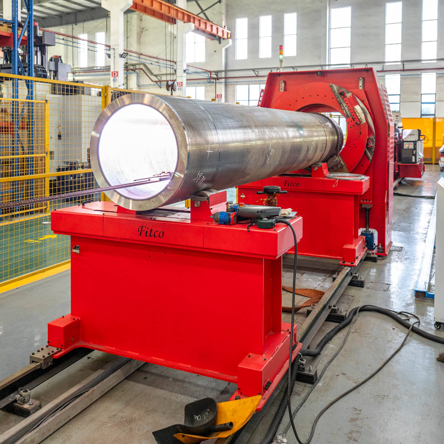
In precision welding applications where joint integrity and structural depth matter most, plasma arc welding stands apart as one of the most capable processes available to industrial fabricators. Unlike conventional arc welding methods that rely on surface fusion alone, plasma arc welding achieves exceptional penetration depths by concentrating thermal energy into a highly focused, high-velocity plasma column. This unique characteristic makes it the process of choice for aerospace components, pressure vessels, titanium fabrication, and any application where a full-penetration weld on thicker materials is required in a single pass.
Central to deep-penetration plasma arc welding is the keyhole technique — a phenomenon where the arc's intense energy density literally pierces through the base material, forming a channel of vaporized metal that travels ahead of the weld pool. Understanding how this keyhole mode works, what conditions enable it, and how to control it effectively is essential knowledge for any welding engineer or fabrication professional looking to exploit the full potential of plasma arc welding in demanding production environments.
The Science Behind the Keyhole Effect in Plasma Arc Welding
How the Keyhole Mode Differs from Melt-In Welding
Plasma arc welding operates in two distinct modes: melt-in mode and keyhole mode. In melt-in mode, the arc melts the base material progressively along the surface, similar to TIG welding but with a more constricted arc. Keyhole mode, however, occurs when the plasma energy density exceeds the threshold required to vaporize material at the point of impingement, forming a through-hole — the keyhole — that penetrates the full thickness of the workpiece.
The keyhole is maintained dynamically as the torch advances. Molten metal flows around the keyhole and solidifies behind it, creating a weld bead with complete root penetration. This mechanism is fundamentally different from surface-fusing processes and explains why plasma arc welding can achieve full-penetration welds on materials up to 8–10 mm thick in a single pass without backing strips or edge preparation that would be required by other methods.
The physics governing keyhole formation involve a precise balance between arc pressure, surface tension of the molten metal, and heat input rate. Too little energy and the keyhole collapses into melt-in mode; too much and the keyhole becomes unstable, leading to irregular bead geometry or porosity. Mastery of plasma arc welding begins with understanding this balance.
The Role of the Plasma Gas Column in Penetration Depth
The plasma arc is generated when a gas — typically argon or a mixture of argon and hydrogen — is forced through a constricting nozzle orifice and subjected to the arc discharge. This constriction forces the ionized gas into a tightly collimated, high-temperature, high-velocity column that transfers energy with a power density far exceeding that of a standard TIG arc. It is this concentration of thermal energy that makes deep penetration possible in plasma arc welding.
The plasma gas flow rate directly influences the mechanical force exerted on the weld pool. Higher plasma gas flow rates increase arc stiffness and penetrating force, promoting keyhole formation. However, excessively high flow rates can cause turbulence at the keyhole entrance, leading to instability. Experienced welding engineers fine-tune the plasma gas flow as part of parameter development to achieve stable, reproducible keyhole conditions for each material and thickness combination.
Shielding gas, typically argon applied through an outer annular nozzle, protects the weld pool and the emerging keyhole from atmospheric contamination. The interaction between plasma gas pressure and shielding gas behavior at the weld surface is another variable that skilled plasma arc welding practitioners manage carefully to avoid oxidation and ensure smooth bead profiles.
Key Parameters That Control Deep Penetration in Plasma Arc Welding
Welding Current and Its Direct Impact on Keyhole Stability
Welding current is arguably the most influential parameter in plasma arc welding when targeting keyhole-mode operation. As current increases, the arc's power density rises, expanding the plasma column's temperature and mechanical force on the base material. For a given material thickness, there is a minimum current threshold below which keyhole formation cannot be sustained and a maximum above which the keyhole becomes excessively large and unstable.
Pulse current techniques are frequently employed in plasma arc welding to improve keyhole stability, particularly on materials prone to distortion or heat sensitivity such as stainless steel and titanium alloys. Pulsing alternates between a peak current that drives the keyhole open and a background current that allows the molten pool to partially solidify, maintaining positional control and reducing the risk of blow-through on thinner sections.
Current selection must also account for joint configuration. Butt joints on flat plates behave differently from T-joints or pipe circumferential welds. In each case, plasma arc welding parameter development requires systematic testing to establish the current band that produces stable, full-penetration keyhole welds with acceptable surface bead geometry and internal soundness.
Travel Speed and Heat Input Management
Travel speed governs how long any given point on the workpiece is subjected to arc heat. In plasma arc welding keyhole applications, travel speed must be matched carefully to the current and plasma gas flow to maintain the keyhole as a stable, moving entity rather than a stationary cavity that can cause excessive burn-through. Slower travel speeds allow more heat to accumulate, which can be beneficial for thicker sections but detrimental for heat-sensitive materials.
The relationship between travel speed and penetration in plasma arc welding is not purely linear. At very high travel speeds, the keyhole may not fully form because the arc does not dwell long enough to vaporize material through the full thickness. At optimized speeds, the keyhole travels with the torch in a controlled manner, producing consistent penetration and bead width. Finding this optimized window is a critical step in any plasma arc welding procedure qualification.
Heat input calculations — expressed as joules per millimeter — are used in plasma arc welding procedure development to ensure compliance with material-specific heat input limits defined in applicable welding codes. Managing heat input through travel speed adjustments is often preferable to current changes because it allows finer control of the keyhole without disrupting the established plasma gas dynamics.
Plasma Orifice Diameter and Nozzle Geometry
The constricting orifice in the plasma torch nozzle is a defining design element that distinguishes plasma arc welding from other arc processes. A smaller orifice diameter produces a more constricted arc with higher power density and greater penetrating capability at equivalent currents. However, smaller orifices are more susceptible to double-arc conditions — an electrical discharge between the electrode and the nozzle rather than the workpiece — which can cause rapid nozzle erosion and arc instability.
Nozzle geometry, including the convergence angle and the exit shape, influences how the plasma gas expands after leaving the orifice. Well-designed plasma arc welding torches optimize this geometry to maintain arc stability across the operating current and flow range specified for a given application. Selecting the correct nozzle for the intended material and thickness is as important as selecting the correct welding parameters.
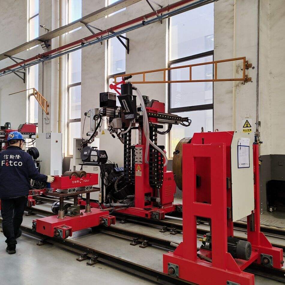
Torch standoff distance — the gap between the nozzle face and the workpiece — also interacts with nozzle geometry. In plasma arc welding, maintaining a consistent standoff is critical for reproducible keyhole behavior. Automated systems with torch height control are preferred in production environments to ensure that standoff variation does not disrupt the delicate energy balance required for stable keyhole operation.
Material Suitability and Applications for Keyhole Plasma Arc Welding
Metals That Benefit Most from Deep Penetration Plasma Arc Welding
Stainless steel is perhaps the most widely welded material using the plasma arc welding keyhole process. The material's moderate thermal conductivity and good fluidity of the weld pool make it well-suited to keyhole operation. Single-pass full-penetration welds on austenitic stainless steel up to 8 mm thick are routinely achieved using plasma arc welding, eliminating multiple-pass sequences and the associated risk of sensitization in the heat-affected zone.
Titanium and titanium alloys respond exceptionally well to plasma arc welding because the process's focused heat input minimizes the width of the heat-affected zone, reducing the risk of alpha-case formation and grain growth that degrade mechanical properties. The clean, inert atmosphere maintained by the shielding gas also prevents the reactive contamination that titanium is prone to at elevated temperatures.
Nickel alloys, duplex stainless steels, and carbon steels in the mid-thickness range also benefit significantly from plasma arc welding keyhole capability. In each case, the reduced number of passes compared to TIG or MIG welding decreases total heat input and distortion, leading to components that are closer to final dimensional tolerance immediately after welding.
Industry Applications Where Keyhole Penetration Delivers Competitive Advantage
The aerospace sector relies heavily on plasma arc welding for structural components and engine casings where weld quality must meet stringent radiographic and mechanical test criteria. The ability to produce full-penetration welds with a narrow fusion zone and minimal distortion gives plasma arc welding a distinct advantage over competing processes in this environment.
In the oil and gas industry, pressure vessels and pipeline components demand complete joint penetration to withstand internal pressure loading and fatigue cycling. Plasma arc welding in keyhole mode delivers these requirements reliably and with high productivity, particularly in automated or mechanized configurations where parameters can be maintained with precision over long weld lengths.
Medical device manufacturing, semiconductor equipment fabrication, and food processing equipment production all employ plasma arc welding for its cleanliness, precision, and ability to produce high-integrity joints on thin to medium thickness materials without the filler metal dependency that can complicate weld chemistry control in critical applications.
Process Control and Quality Assurance in Keyhole Plasma Arc Welding
Monitoring Keyhole Stability During Welding
One of the challenges of plasma arc welding in keyhole mode is that the keyhole itself is not directly visible to the welder under normal operating conditions. Arc voltage monitoring is commonly used as an indirect indicator of keyhole status — a stable arc voltage corresponds to a stable keyhole, while voltage excursions indicate keyhole collapse or instability. Advanced plasma arc welding systems incorporate real-time voltage and current feedback to detect and correct parameter drift before weld quality is compromised.
Acoustic emission monitoring has emerged as a complementary technique, exploiting the distinctive sound signature of a stable keyhole plasma arc welding process versus an unstable one. Combined with machine vision systems that observe the rear face of the weld for keyhole light emission, these monitoring approaches provide a multi-sensor quality assurance framework well suited to automated production environments.
Weld pool observation through filtered optical systems allows experienced operators to identify early signs of keyhole instability such as humping, undercut, or irregular bead width. In manual or semi-automatic plasma arc welding setups, operator skill in recognizing and responding to these visual cues remains an important quality control mechanism alongside instrumented monitoring.
Post-Weld Inspection and Acceptance Criteria
Full-penetration welds produced by plasma arc welding are typically subject to radiographic testing, ultrasonic testing, or both, depending on the applicable code and criticality of the joint. The narrow, columnar weld profile characteristic of keyhole plasma arc welding presents a favorable inspection signature because the fusion zone is well-defined and the heat-affected zone is narrow, making defects easier to locate and characterize.
Common acceptance criteria for plasma arc welding keyhole welds include limits on porosity, lack of fusion, root concavity, and excess penetration. Root concavity is a particular concern in keyhole welding because the keyhole closure mechanism can leave a slight depression on the reverse face if parameters are not optimized. Controlled plasma gas flow reduction at the end of the weld or programmed current downslope routines are used to close the keyhole cleanly and avoid this defect.
Hardness testing across the weld cross-section provides additional quality data, particularly for materials where heat-affected zone hardness is a concern. The generally lower heat input of plasma arc welding compared to multi-pass processes means that hardness peaks in the heat-affected zone are often lower, an advantage that simplifies compliance with hardness limits in structural and pressure equipment codes.
FAQ
What thickness range is suitable for keyhole plasma arc welding?
Keyhole plasma arc welding is most effectively applied to materials in the 2 mm to 10 mm thickness range for stainless steel, with titanium and nickel alloys often welded in similar thickness brackets. Below 2 mm, melt-in mode is generally preferred because the energy required to sustain a keyhole can cause excessive burn-through. Above 10 mm, multi-pass plasma arc welding or hybrid processes are typically used, though specialized high-current systems can achieve keyhole penetration on thicker sections under carefully controlled conditions.
How does plasma arc welding compare to laser welding for deep penetration applications?
Both plasma arc welding and laser welding can achieve deep penetration through keyhole mechanisms, but they differ significantly in equipment cost, operational flexibility, and tolerance to joint fit-up variation. Plasma arc welding is considerably less expensive to implement and maintain, tolerates wider joint gaps, and is more adaptable to field and workshop environments. Laser welding offers faster travel speeds and even narrower heat-affected zones on thinner materials, but requires precise fixturing and clean joint surfaces. For many industrial applications, plasma arc welding delivers a highly competitive combination of penetration capability and process flexibility at substantially lower capital cost.
What gases are used in keyhole plasma arc welding and why?
Argon is the most common plasma gas used in plasma arc welding due to its reliable arc starting characteristics, stable arc behavior, and inert shielding properties. For applications requiring greater penetration on austenitic stainless steel or nickel alloys, small additions of hydrogen — typically 5 to 15 percent — are made to the plasma gas, increasing arc enthalpy and improving fusion penetration. Helium additions are used in some plasma arc welding applications to increase heat transfer efficiency. The shielding gas is almost always pure argon or argon-helium mixtures chosen to protect the weld pool from atmospheric contamination without interfering with keyhole stability.
Can plasma arc welding be automated for production keyhole welding?
Yes, plasma arc welding is highly amenable to automation and is routinely implemented in mechanized and fully automated configurations for production keyhole welding. Automated plasma arc welding systems can maintain arc length, travel speed, and gas flow with a precision that is difficult to achieve manually, resulting in highly consistent weld quality across long production runs. Robotic plasma arc welding cells are used in aerospace, automotive, and pressure vessel manufacturing, often integrated with real-time monitoring systems that detect parameter deviations and trigger corrective action or weld rejection protocols, ensuring that every weld meets the defined quality standard.