
 EN
EN
 AR
AR BG
BG HR
HR CS
CS DA
DA NL
NL FI
FI FR
FR DE
DE EL
EL HI
HI IT
IT JA
JA KO
KO NO
NO PL
PL PT
PT RO
RO RU
RU ES
ES SV
SV TL
TL IW
IW ID
ID LT
LT UK
UK SQ
SQ HU
HU TH
TH TR
TR FA
FA AF
AF CY
CY MK
MK LA
LA MN
MN KK
KK UZ
UZ KY
KY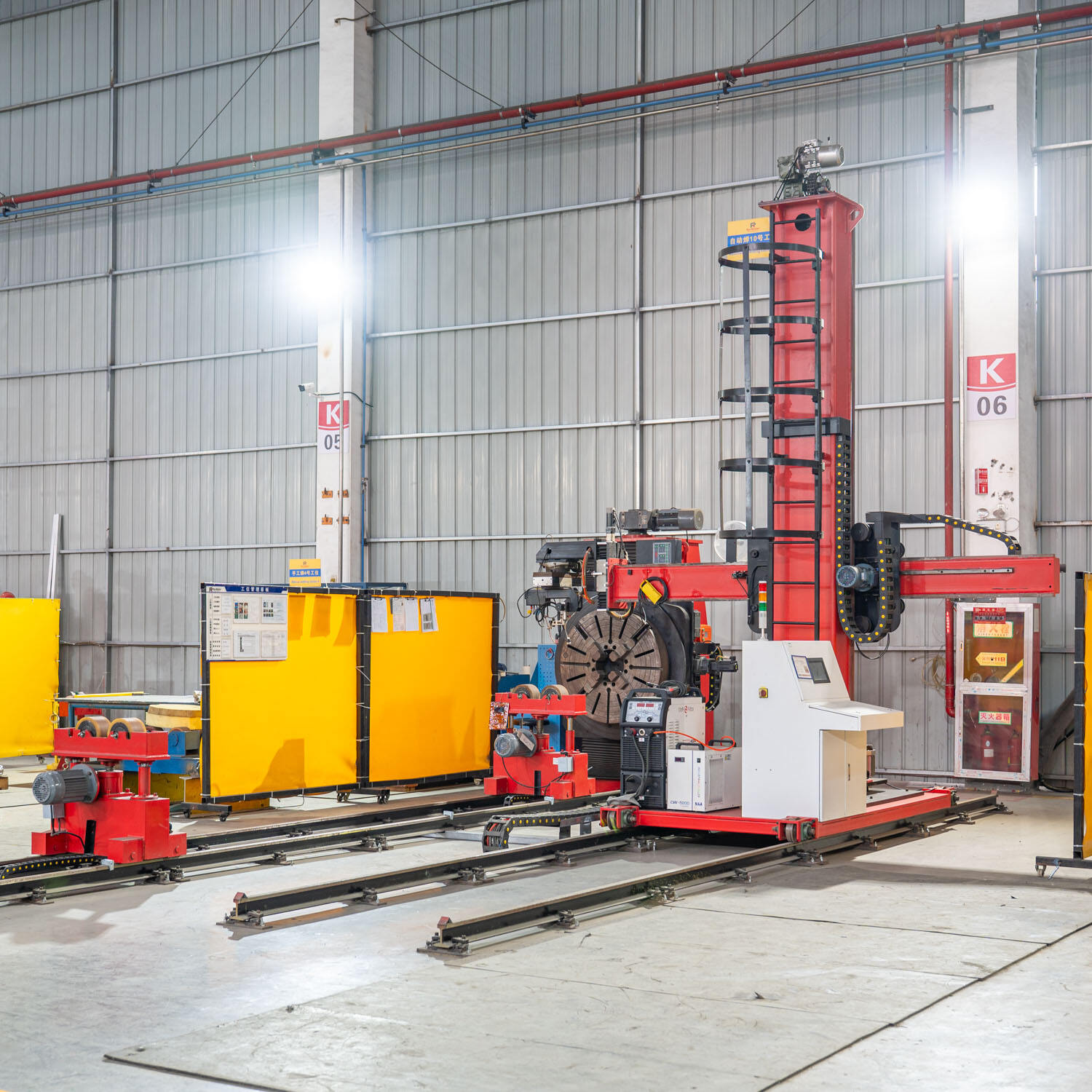
Aerospace manufacturing demands perfection at every stage, and tube welding represents one of the most critical operations where quality cannot be compromised. Traditional manual welding methods introduce human variability that can lead to inconsistent weld penetration, unpredictable heat input, and structural weaknesses in aerospace tube assemblies. As aerospace systems require tubes that carry hydraulic fluids, fuel, oxygen, and other critical substances under extreme pressure and temperature conditions, the consequences of weld defects can be catastrophic. This is precisely where orbital welding technology transforms aerospace tube fabrication by eliminating human inconsistency and delivering repeatability that meets stringent aerospace quality standards.
The fundamental mechanism through which orbital welding ensures consistent quality lies in its automated, computer-controlled approach to joining aerospace tubes. Unlike manual TIG welding where the welder's hand steadiness, travel speed, and arc length vary from one weld to the next, orbital welding systems rotate a precisely controlled tungsten electrode around a stationary tube workpiece following programmed parameters. This automation removes operator skill variation as the dominant quality factor, replacing it with programmable parameters that can be validated, documented, and reproduced across thousands of identical welds. For aerospace manufacturers working under AS9100 certification and facing stringent FAA oversight, this transition from operator-dependent to process-dependent quality represents a fundamental shift in how tube weld integrity is achieved and verified.
The Precision Control Architecture Behind Consistent Aerospace Tube Welds
Programmable Parameter Management in Orbital Welding Systems
Orbital welding achieves consistency through comprehensive parameter control that governs every aspect of the weld cycle. Modern orbital welding power sources allow engineers to program welding current ramp-up profiles, maintain precise arc voltage throughout the rotation, control torch travel speed with sub-millimeter accuracy, and manage shielding gas flow rates that protect the weld zone from atmospheric contamination. These parameters are stored digitally as weld schedules specific to each tube material, wall thickness, and diameter combination used in aerospace applications. When a technician initiates an orbital welding operation on a titanium hydraulic tube with a specific wall thickness, the system retrieves the validated weld schedule and executes it with mechanical precision, ensuring that weld number one and weld number one thousand receive identical heat input, fusion characteristics, and penetration depth.
The closed-loop feedback systems integrated into advanced orbital welding equipment further enhance consistency by monitoring real-time weld conditions and making micro-adjustments during the weld cycle. Arc voltage monitoring detects variations in electrode-to-work distance caused by tube ovality or fixture positioning, automatically adjusting current output to maintain consistent heat input. This adaptive control compensates for minor variations in component fit-up that would cause significant quality problems in manual welding, where the operator might not detect subtle arc length changes until visible defects appear. For aerospace tube assemblies where a single weak weld can compromise an entire fuel system or hydraulic circuit, this level of automated process control transforms quality assurance from post-weld inspection to in-process prevention.
Mechanical Repeatability Through Fixed Orbital Rotation
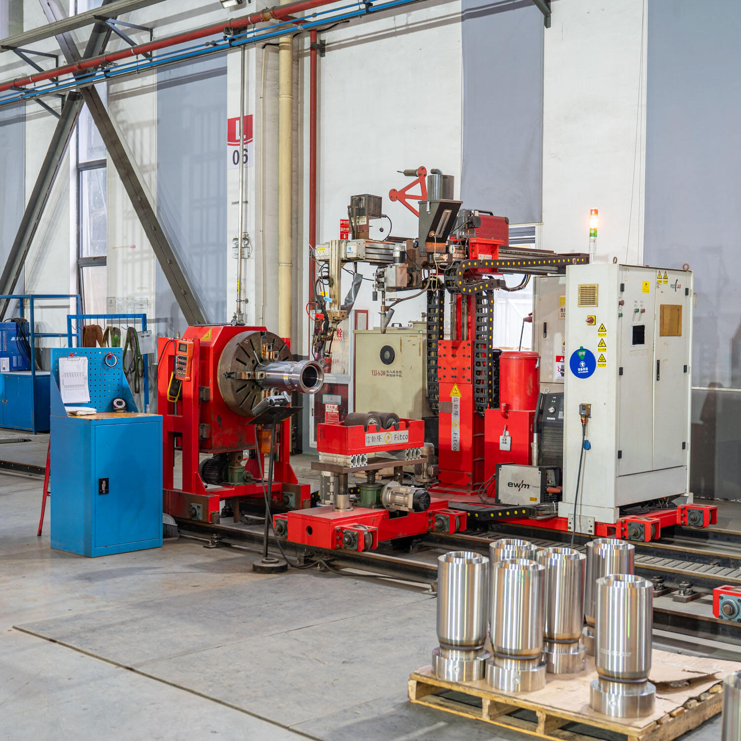
The mechanical foundation of orbital welding consistency lies in the fixed rotation system that carries the welding torch around the tube circumference. Unlike manual welding where the operator's hand follows an imperfect circular path with variable speed and changing torch angle, orbital welding heads employ precision gear-driven or servo-controlled rotation mechanisms that maintain exact torch positioning throughout the 360-degree travel. The torch maintains a constant stick-out distance, consistent travel angle, and uniform speed that eliminates the wavering arc behavior inherent to hand-guided welding. This mechanical stability is particularly crucial for aerospace tubes in the 0.25-inch to 2-inch diameter range, where small deviations in torch position create disproportionate heat input variations that affect penetration uniformity and microstructure consistency.
Aerospace manufacturers benefit from orbital welding repeatability when producing tube assemblies with multiple identical joints, such as manifold systems with dozens of branch connections or landing gear hydraulic circuits with numerous tube-to-fitting welds. Each weld receives identical torch positioning, travel speed, and heat input, resulting in mechanical properties that fall within narrow statistical ranges rather than the wide distributions typical of manual welding operations. This consistency extends to visual weld appearance, with orbital welding producing uniform bead profiles, consistent ripple patterns, and predictable weld reinforcement geometry that simplifies visual inspection and reduces the ambiguity that often accompanies manual weld evaluation. When aerospace quality inspectors examine orbital welded tube assemblies, they observe remarkable uniformity that provides confidence in structural integrity even before non-destructive testing begins.
Material-Specific Quality Advantages in Aerospace Tube Applications
Titanium Tube Welding Consistency and Contamination Control
Titanium alloys dominate aerospace hydraulic and fuel tube applications due to their exceptional strength-to-weight ratio and corrosion resistance, yet these same materials present significant welding challenges that orbital welding technology directly addresses. Titanium's extreme reactivity with atmospheric gases at welding temperatures means that any breach in shielding gas coverage produces contamination that embrittles the weld zone and creates rejection-level defects. Manual welding of titanium tubes requires extraordinary operator skill to maintain consistent shielding gas coverage while manipulating the torch around the tube circumference, and even experienced welders produce titanium welds with variable contamination levels that appear as discoloration ranging from silver to blue, gold, and unacceptable purple or white oxidation.
Orbital welding eliminates this contamination variability through enclosed weld head designs that create a complete inert atmosphere around the weld zone. The weld head chamber is purged with argon before arc initiation, and the controlled rotation maintains this protective environment throughout the complete circumferential travel. Trailing shields integrated into the orbital welding head extend shielding gas coverage behind the arc as the weld metal cools through the critical temperature range where contamination occurs. This comprehensive gas coverage produces titanium aerospace tube welds with consistent silver coloration indicating complete atmospheric exclusion, eliminating the contamination-related rejections that plague manual titanium welding operations. For aerospace manufacturers working with Grade 9 titanium hydraulic tubes or Grade 5 titanium fuel lines, orbital welding transforms titanium joining from a high-skill, high-rejection operation into a predictable, repeatable process.
Stainless Steel Aerospace Tube Consistency and Sensitization Control
Stainless steel tubes used in aerospace pneumatic systems, environmental control circuits, and auxiliary power units require orbital welding precision to avoid sensitization and maintain corrosion resistance throughout the weld zone. The heat-affected zone adjacent to welds in 300-series stainless steels can experience chromium carbide precipitation when exposed to temperatures in the critical 800-to-1500 degree Fahrenheit range for extended periods, depleting chromium content along grain boundaries and creating paths for intergranular corrosion. Manual welding of stainless steel aerospace tubes produces variable heat input that exposes different circumferential segments to different thermal histories, resulting in inconsistent sensitization risk around the tube perimeter and unpredictable corrosion performance in service.
Orbital welding controls heat input uniformity around the entire tube circumference, ensuring that every segment of the weld zone experiences the same thermal cycle and achieves similar metallurgical outcomes. The programmed travel speed and consistent arc energy prevent the excessive heat input that occurs when manual welders slow their travel rate, and the continuous rotation eliminates the start-stop thermal discontinuities that create localized overheating. This thermal consistency is particularly valuable for aerospace stainless steel tubes in corrosive service environments, such as environmental control system condensate lines or auxiliary power unit fuel tubes, where localized sensitization can initiate corrosion failures that compromise system integrity. Aerospace quality engineers recognize that orbital welding produces stainless steel tube welds with uniform corrosion resistance characteristics, eliminating the weak zones that can develop in manually welded assemblies.
Process Documentation and Traceability Supporting Aerospace Quality Systems
Automated Weld Data Logging and Parameter Verification
Aerospace manufacturing operates under comprehensive quality management systems that require complete documentation of critical processes, and orbital welding technology provides inherent traceability advantages that support these documentation requirements. Modern orbital welding power sources incorporate data logging capabilities that automatically record every weld parameter throughout each weld cycle, capturing actual current values, voltage readings, travel completion status, and any fault conditions that occurred during execution. This automated documentation replaces the manual weld logs common in traditional aerospace welding operations, where welders record parameters by hand with inevitable transcription errors and incomplete data capture that complicate quality investigations when defects appear downstream.
The digital weld records generated by orbital welding systems create an objective foundation for aerospace quality traceability, linking each tube weld to specific parameter values, equipment serial numbers, operator identifications, and weld procedure specifications. When an aerospace tube assembly undergoes final inspection or encounters service issues years after fabrication, quality engineers can retrieve the exact orbital welding parameters used for each joint and verify that the prescribed weld schedule was executed correctly. This documentation capability satisfies AS9100 requirements for objective evidence of process control and provides the forensic data needed when weld-related failures occur in service. Aerospace manufacturers implementing orbital welding technology gain quality system advantages that extend beyond improved weld consistency to encompass the comprehensive traceability that aerospace customers and regulatory authorities demand.
Weld Procedure Qualification and Reproducibility
The aerospace industry requires formal weld procedure qualification following AWS D17.1 or similar aerospace welding standards, and orbital welding technology facilitates the development and validation of procedures that deliver consistent results across production quantities. Procedure qualification for orbital welding involves establishing the specific parameter combinations that produce acceptable welds for each material-thickness-diameter combination used in aerospace tube assemblies, then documenting these parameters as locked weld schedules that cannot be altered without formal engineering authorization. This approach contrasts sharply with manual welding procedure qualification, where the procedure provides parameter ranges rather than exact values, acknowledging that each welder will execute the procedure somewhat differently based on their individual technique and real-time observations.
Once an orbital welding procedure is qualified through mechanical testing, metallographic examination, and non-destructive evaluation of qualification test welds, aerospace manufacturers gain confidence that production welds made using the identical parameters will exhibit the same mechanical properties, microstructure characteristics, and defect resistance demonstrated during qualification. This reproducibility eliminates the variation between qualification test results and production weld quality that often occurs with manual welding, where qualification coupons are typically welded by the most skilled operators under ideal conditions while production welds are completed by a wider range of welders under time pressure and production constraints. Orbital welding ensures that the weld quality demonstrated during procedure qualification translates directly to production aerospace tube assemblies without degradation from operator skill variation or inconsistent execution.
Non-Destructive Testing Reliability Enhanced by Orbital Welding Consistency
Radiographic Inspection Confidence and Defect Detection
Aerospace tube welds undergo radiographic inspection to detect internal defects such as incomplete fusion, porosity, and inclusions that compromise structural integrity, and orbital welding consistency directly enhances the reliability of radiographic evaluation. Manual welds present inspection challenges because weld quality varies around the tube circumference, requiring radiographers to capture multiple exposures at different angular orientations to ensure complete coverage of potential defect zones. The variable penetration depth, bead geometry, and fusion characteristics typical of manual tube welds create radiographic images with inconsistent density patterns that complicate defect interpretation and increase the likelihood that subtle indications are missed or misclassified during film evaluation.
Orbital welding produces circumferentially uniform welds that generate consistent radiographic density patterns, allowing inspectors to identify genuine defects more readily against the predictable background image. The uniform penetration achieved through controlled orbital welding parameters means that any area of reduced density on the radiograph represents an actual defect rather than normal penetration variation, reducing false calls and improving inspection throughput. For aerospace manufacturers producing high volumes of tube assemblies with hundreds of welded joints, the improved radiographic inspectability of orbital welding translates to faster inspection cycles, higher defect detection rates, and reduced costs associated with unnecessary weld repairs prompted by ambiguous radiographic indications. This inspection advantage complements the inherent quality consistency of orbital welding by ensuring that the rare defects that do occur are reliably detected before defective assemblies reach flight-critical aerospace applications.
Ultrasonic and Penetrant Testing Baseline Consistency
Ultrasonic testing of aerospace tube welds relies on establishing baseline signal characteristics for acceptable welds, then identifying deviations that indicate defects, and orbital welding uniformity provides the stable baseline needed for accurate ultrasonic evaluation. Manual welds exhibit variable grain structure, penetration depth, and bead geometry around the tube circumference, creating ultrasonic signal variations that complicate the distinction between normal structural variation and actual defects. Ultrasonic inspectors examining manually welded aerospace tubes must account for wide signal amplitude ranges and changing waveform characteristics as the transducer moves around the weld, reducing sensitivity to subtle defects that produce signals within the normal variation envelope.
The metallurgical consistency achieved through orbital welding produces uniform ultrasonic response characteristics around the entire tube circumference, allowing inspectors to use tighter acceptance criteria and detect smaller defects with higher confidence. Ultrasonic signals from orbital welded joints exhibit narrow amplitude distributions and consistent waveform morphology that simplify calibration and reduce inspection time while improving defect detection capability. Similarly, liquid penetrant inspection of aerospace tube welds benefits from orbital welding consistency because the uniform surface finish and consistent bead geometry eliminate the surface irregularities that can trap penetrant and produce false indications in manual welds. For aerospace quality assurance programs that rely on multiple complementary non-destructive testing methods to verify tube weld integrity, orbital welding enhances the effectiveness of each inspection technique through the fundamental consistency of the welded joints being evaluated.
Long-Term Service Reliability and Fatigue Performance Benefits
Fatigue Resistance Through Consistent Weld Geometry
Aerospace tube assemblies in landing gear systems, flight control actuators, and engine fuel delivery circuits experience cyclic loading throughout their service life, and weld quality consistency directly influences fatigue crack initiation resistance. Fatigue cracks in welded tubes typically initiate at geometric stress concentrations such as weld toe transitions, weld root irregularities, or areas of incomplete fusion where local stress exceeds the material's endurance limit under repeated loading cycles. Manual welding produces variable weld bead profiles with inconsistent toe angles, irregular ripple patterns, and localized areas of excessive reinforcement or inadequate fusion that create stress concentration variations around the tube circumference. These geometric inconsistencies mean that different angular positions around manually welded tubes exhibit different fatigue resistance, with crack initiation occurring first at the weakest location.
Orbital welding eliminates this circumferential variation in fatigue performance by producing uniform weld bead geometry with consistent toe transitions, predictable reinforcement height, and smooth surface profiles that minimize stress concentration. The controlled heat input and steady travel speed inherent to orbital welding generate weld beads with symmetrical cross-sections and regular ripple spacing that distribute stresses evenly around the tube perimeter. Fatigue testing of orbital welded aerospace tubes demonstrates that crack initiation occurs at similar cycle counts regardless of circumferential position, and the overall fatigue life exceeds that of comparable manually welded joints because the most vulnerable locations in orbital welds are less severe than the worst-case stress risers present in manual welds. For aerospace systems where tube joint failures can result in hydraulic fluid loss, fuel leakage, or flight control degradation, the improved fatigue reliability achieved through orbital welding consistency provides a direct safety benefit that justifies the technology investment.
Corrosion Resistance Uniformity in Service Environments
Aerospace tube systems operate in corrosive environments including salt-laden maritime atmospheres, de-icing chemical exposure, and hydraulic fluid contamination, and orbital welding consistency ensures uniform corrosion resistance around welded tube joints. Corrosion in welded aerospace tubes typically initiates at locations where welding heat input has altered the material's protective characteristics, such as sensitized zones in stainless steel, depleted regions in aluminum alloys, or contaminated areas in titanium where atmospheric exposure during welding compromised the oxide film. Manual welding produces variable heat input around the tube circumference, creating zones of differential corrosion susceptibility where localized attack can initiate pitting, crevice corrosion, or stress corrosion cracking that propagates through the tube wall.
The uniform thermal cycle delivered by orbital welding ensures that every angular position around aerospace tube welds experiences similar metallurgical changes and maintains equivalent corrosion resistance. Electrochemical testing of orbital welded joints reveals narrow distributions of corrosion potential and passive film stability around the weld circumference, contrasting with the wide variations observed in manually welded samples where some zones show significantly degraded corrosion resistance. This uniformity means that orbital welded aerospace tubes resist localized corrosion initiation and exhibit longer service life in corrosive environments compared to manually welded assemblies where the weakest zones control overall durability. Aerospace maintenance organizations report reduced corrosion-related tube replacements when systems incorporate orbital welded joints, validating the long-term service reliability advantages that stem from the consistent quality achieved through orbital welding technology.
FAQ
What makes orbital welding more consistent than manual TIG welding for aerospace tubes?
Orbital welding achieves superior consistency through automated parameter control and mechanized torch rotation that eliminate human variability. While manual TIG welding depends on the operator's ability to maintain steady hand movement, consistent travel speed, and uniform arc length throughout the weld, orbital welding systems execute programmed parameters with mechanical precision. The fixed rotation mechanism carries the torch around the tube at constant speed with unchanging electrode positioning, while the power source maintains precise current and voltage control throughout the complete 360-degree travel. This automation removes operator skill level, fatigue, and technique variation as quality factors, replacing them with validated weld schedules that produce identical results across thousands of aerospace tube welds. The result is circumferentially uniform penetration, consistent heat-affected zone width, and predictable mechanical properties that meet aerospace quality requirements without the statistical variation inherent to manual welding processes.
Can orbital welding handle the different aerospace tube materials and wall thicknesses consistently?
Modern orbital welding systems accommodate the full range of aerospace tube materials and dimensions through programmable weld schedules optimized for each specific combination. Aerospace tube assemblies utilize materials from titanium alloys and stainless steels to nickel-based superalloys and aluminum, with wall thicknesses ranging from thin-wall 0.020-inch tubing to heavy-wall 0.125-inch and thicker structural tubes. Orbital welding power sources store multiple weld programs that specify appropriate current levels, pulse parameters, travel speeds, and gas flow rates for each material-thickness combination, allowing operators to select the correct schedule for the specific aerospace tube being welded. The key to consistent quality across this material and thickness range lies in proper weld procedure development and qualification, where engineering teams establish and validate the parameters that produce acceptable welds for each configuration. Once qualified, these parameters are locked into the orbital welding system and executed with the same mechanical precision regardless of whether the application involves thin-wall titanium hydraulic tubes or thick-wall stainless steel manifold connections.
How does orbital welding consistency affect aerospace tube assembly production costs?
The consistency achieved through orbital welding significantly reduces aerospace tube assembly production costs despite higher initial equipment investment compared to manual welding stations. Orbital welding eliminates the high rejection rates that occur when manual welders produce out-of-specification joints due to inconsistent technique or challenging welding positions, reducing scrap costs and rework labor. The uniform quality of orbital welding also streamlines inspection processes because radiographers, ultrasonic technicians, and visual inspectors spend less time evaluating ambiguous indications and distinguishing normal variation from actual defects. Production planning becomes more predictable when orbital welding eliminates the schedule disruptions caused by unexpected manual weld failures discovered during final inspection. Labor costs decrease because orbital welding operators require less extensive training than certified manual aerospace welders, and a single operator can often monitor multiple orbital welding systems simultaneously. Quality system costs also decline because the automated documentation inherent to orbital welding reduces the manual record-keeping and data transcription required for aerospace traceability compliance. When aerospace manufacturers calculate total cost of ownership over multi-year production runs, orbital welding typically delivers lower per-assembly costs while simultaneously improving quality consistency.
Does orbital welding require special operator certification for aerospace applications?
Aerospace orbital welding operators require certification that demonstrates their competency in equipment setup, program selection, joint preparation, and quality verification, though the certification process differs from traditional manual welder qualification. Rather than testing the operator's hand welding technique and arc manipulation skill, orbital welding certification focuses on the operator's ability to correctly prepare tube ends, align components in the welding fixture, select appropriate weld programs, initiate the automated weld cycle, and inspect completed welds for conformance to acceptance criteria. The certification typically follows AWS B2.1 or similar standards adapted for orbital welding processes, requiring operators to produce test welds that meet specified quality requirements under observation by a certified welding inspector. Some aerospace manufacturers implement internal orbital welding operator certification programs tailored to their specific equipment and applications, while others utilize third-party certification services. The key distinction is that orbital welding certification validates process execution capability rather than manual dexterity, recognizing that weld quality depends primarily on correct parameter selection and equipment setup rather than operator technique during the actual welding arc time.
Table of Contents
- The Precision Control Architecture Behind Consistent Aerospace Tube Welds
- Material-Specific Quality Advantages in Aerospace Tube Applications
- Process Documentation and Traceability Supporting Aerospace Quality Systems
- Non-Destructive Testing Reliability Enhanced by Orbital Welding Consistency
- Long-Term Service Reliability and Fatigue Performance Benefits
-
FAQ
- What makes orbital welding more consistent than manual TIG welding for aerospace tubes?
- Can orbital welding handle the different aerospace tube materials and wall thicknesses consistently?
- How does orbital welding consistency affect aerospace tube assembly production costs?
- Does orbital welding require special operator certification for aerospace applications?